
Introduction
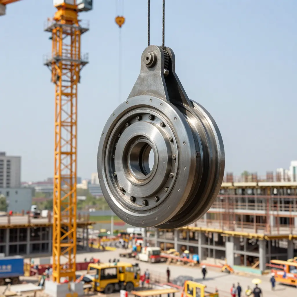
When a tower crane slewing bearing locks up, the crane loses rotation. The jib stops mid-swing while the suspended load keeps moving, and that mismatch between a stationary structure and a moving load is where dropped loads, struck-by injuries, and deformed mast sections originate. The aftermath is its own kind of trouble: the crane comes out of service, the lifting schedule collapses, and the repair usually means heavy rigging work at height.
The bearing rarely seizes without warning. Roller spalling, raceway pitting, and lubricant breakdown each leave a trace in vibration data: rising amplitudes at characteristic frequencies, growing sidebands around the rotation rate, and shock pulses that strengthen week over week. A maintenance team that trends those signals can replace a bearing during a planned outage instead of reacting to a failure at a bad moment.
This article is for construction professionals, crane operators, and maintenance technicians who want to move from reactive repair to condition-based monitoring. It covers how vibration data is captured on a tower crane slew system, how to separate normal operating noise from early-stage wear, how to set alarm thresholds that trigger an inspection rather than a panic, and how to turn a measured signature into a scheduled repair.
How a Slewing Bearing Wears
A tower crane’s slewing ring bearing sits between the fixed base and the rotating superstructure. It lets the jib swing under load and absorbs every force the load applies. Knowing how the bearing wears is the first step toward catching a failure before it becomes a lockup.
Anatomy of the Assembly
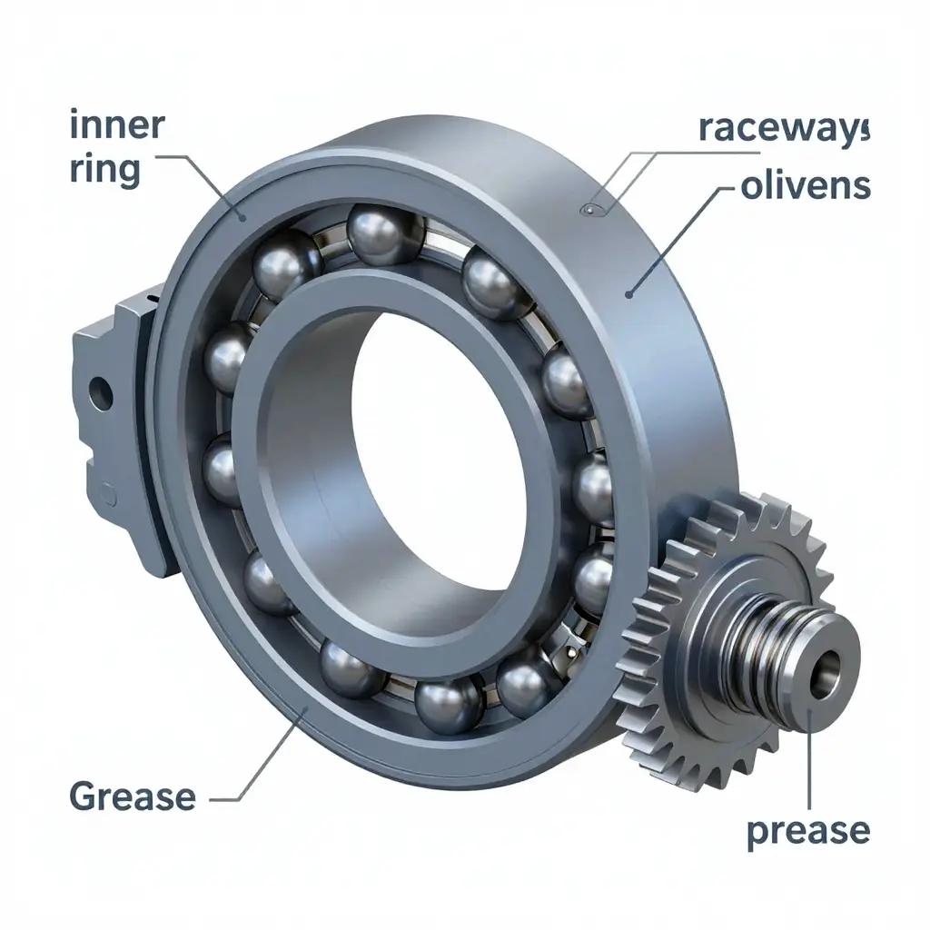
The bearing is a set of concentric rings working as one unit:
- Inner and outer rings – hardened steel rings, one bolted to the base and one to the rotating structure.
- Raceways – precision-ground grooves machined into each ring, the tracks the rolling elements travel along.
- Rolling elements – balls for lighter duty and rollers for heavy cranes, held in place by cages or spacers.
- Gear teeth – external or internal teeth cut into a ring, meshing with the slewing drive pinion that turns the crane.
Each interface carries load: the rings transfer it, the raceways distribute it, the rolling elements bear it, and the teeth convert rotation into motion.
Forces at Play Under Load
A crane’s load is almost never centered. The jib’s offset creates a combination of axial load, radial load, and a large overturning moment that tilts the rings relative to each other. Contact pressures spike at localized points instead of spreading evenly, which makes tower cranes harder on bearings than symmetrical machines.
The Wear Mechanisms
Under repeated stress, several failure modes develop, often at the same time:
- Micro-pitting – tiny surface cracks on the raceway flake away under cyclic contact stress, leaving a dull, frosty finish.
- Spalling – micro-pits grow into larger craters as fatigue reaches the subsurface.
- False brinelling – micro-vibration during idle periods, when the crane sits still but wind makes it rock, creates shallow dents that mimic true brinelling.
- Inadequate lubrication – a thin or starved film lets metal touch metal, accelerating every mechanism above.
- Contamination – grit, water, and metal debris act like an abrasive lapping compound inside the raceway, wearing it away fast.
Vibration Comes First
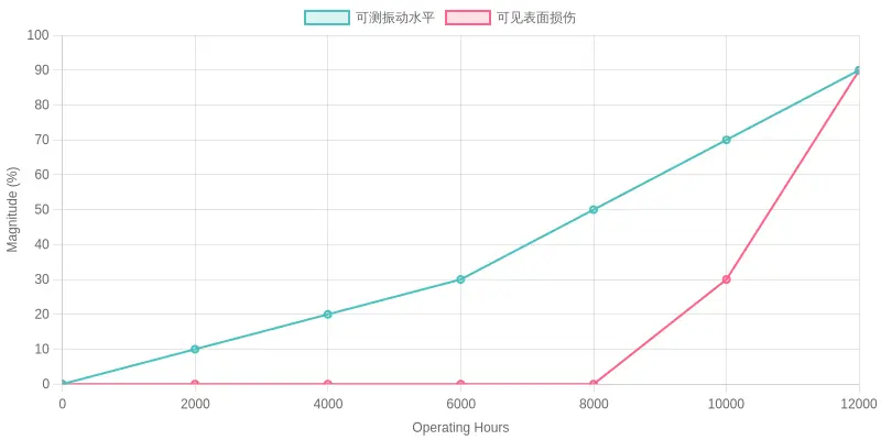
These conditions generate measurable vibration long before they produce visible damage. Raceway wear shows up in the frequency spectrum weeks or months before any dent, stain, or looseness you could spot by eye: first as rising sidebands around the rotational and gear-mesh frequencies, then as a growing low-frequency rumble from the overturning moment.
That early window is where maintenance decisions can still be made. By the time damage is visible on an inspection, the bearing is often already on the path to seizure. Track the trend and you are acting on data instead of a deadline.
Inside the Slewing Ring: Where Wear Starts
Before you trust the numbers coming off a vibration sensor, it helps to know what is inside the bearing you are monitoring. A tower crane slewing ring is a tightly engineered stack of concentric components that rotate the entire upper structure under load.
Reading the schematic
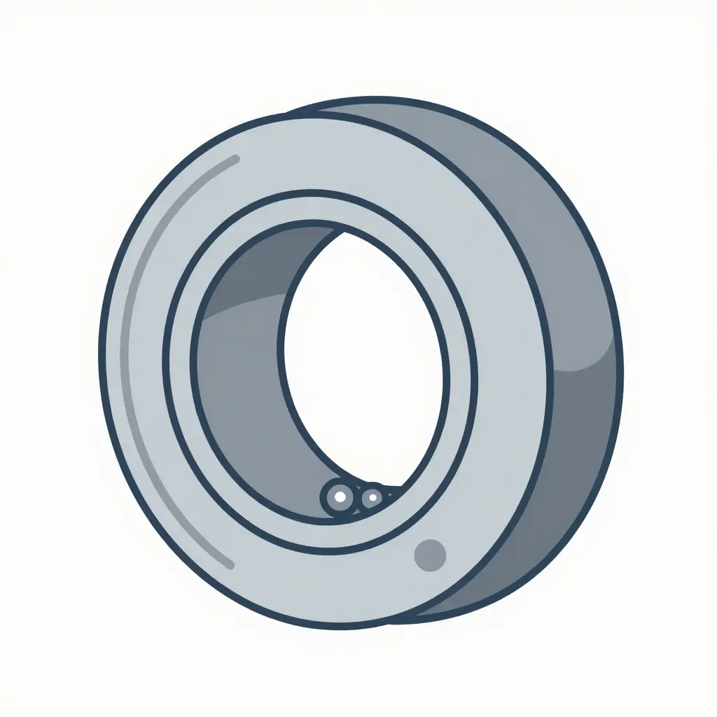
- Inner ring – the rotating or stationary core that seats against the crane’s mounting flange.
- Outer ring – the mating ring that carries the opposing load path and, on many units, the gear teeth.
- Rolling elements – the balls (or rollers) that transfer load between rings while allowing smooth rotation.
- Raceway surfaces – the machined contact tracks the rolling elements ride on; these are the most sensitive wear points.
- Gear teeth – the toothed section that meshes with the slewing drive pinion, translating motor torque into rotation.
The shaded zones mark the three places where degradation most often begins: the raceway contact band, the gear tooth flank, and the ball surface. Keep this geometry in mind as you learn how vibration signatures map to these specific contact points. A spike that looks random on a screen usually traces back to one of these surfaces losing its original profile.
Why Vibration Data Reads the Future
Every rotating and oscillating component in a crane leaves a fingerprint. As the slewing bearing turns, its rolling elements, raceways, and gear teeth generate a characteristic vibration signature: a blend of amplitude, frequency, and harmonic content that stays stable while the machine is healthy.
Vibration analysis captures that baseline and watches for the drift that signals trouble.
When a slewing bearing wears, the signature changes. A small spall on a raceway adds a high-frequency spike. A loosening race or a flat spot shifts the fundamental frequency. Grease starvation and micro-pitting raise the overall amplitude. Each change is measurable weeks or months before a lockup, and none of it is visible to the naked eye.
Condition monitoring makes those changes usable. Accelerometers mounted on the bearing housing are trended over time, turning raw vibration into a health curve: amplitude climbing, harmonic peaks multiplying, frequency bands migrating. A team watching that curve can see how fast a fault is developing.
Reactive maintenance waits for the failure. It responds after the bearing locks, the crane stops, and the site shuts down, which is the most expensive moment to act.
Predictive maintenance flips that sequence: service is scheduled when the data shows wear accelerating, so the bearing is replaced in a planned downtime window rather than an emergency one.
Early Warning Indicators to Watch
Catching slewing bearing wear before it turns into a catastrophic failure comes down to watching the right signals, consistently, over time. No single reading tells the whole story, but the indicators below should put any maintenance team on alert:
- Rising overall vibration levels. A slow, steady upward trend in broadband RMS velocity on the bearing housing or slewing gearbox points to progressive raceway and rolling-element degradation, well before a single dramatic spike appears.
- New sideband frequencies around the gear mesh frequency. Sidebands appearing at the gear mesh frequency plus or minus the rotation speed point to localized load-zone damage that, left unchecked, can march the bearing toward a full lockup.
- Increasing temperature trends. Gradually climbing bearing temperatures, even without a sudden jump, usually reflect rising friction from worn raceways, spalled surfaces, or depleted lubrication.
- Metallic particles in lubricant samples. Rising iron or steel particle counts in grease or oil samples confirm that surfaces inside the bearing are actively wearing and shedding material.
- Uneven slewing motion. Jerky, hesitant, or inconsistent rotation when an operator calls for smooth movement hints at internal binding, pitting, or loss of running clearance.
- Unusual audible noise during start-stop cycles. Grinding, clicking, or clunking sounds at startup and shutdown reveal spalling, cracked races, or loose cage components.
- Elevated shock pulse readings. High shock pulse or envelope-acceleration values indicate repeated mechanical impacts from damaged contact surfaces, catching defects that plain vibration trends can miss.
- Changes in bearing characteristic frequencies. New energy peaks at BPFO, BPFI, or ball-spin frequencies confirm damage that has moved from a general wear pattern into a specific, advancing defect.
- Visible grease discoloration or weeping. Darkened, burnt-smelling grease or seal weeping around the bearing indicates overheating and contamination that accelerate every other failure mode above.
Treat these signals as a tiered warning system: one indicator justifies closer monitoring, two or more justify scheduling an inspection, and any rapid change in trend justifies taking the crane out of service before the bearing seizes.
Not every rumble means the same thing. Matching a frequency signature to the failure mode it points to is what separates a planned repair from a panicked shutdown. Use the table below as a quick field reference when you pull your vibration readings.
| Vibration Signature | Likely Bearing Fault | Urgency Level |
|---|---|---|
| Low-frequency, high-amplitude peaks | Raceway deformation | High – schedule inspection within days |
| High-frequency bursts | Micro-pitting or early spalling | Moderate – trend closely, plan service |
| Elevated gear mesh sidebands | Tooth wear | Moderate – monitor at every shift |
| Random broadband noise floor | Inadequate lubrication | High – lubricate and re-test immediately |
| Periodic, repetitive impacts | Rolling element damage | Critical – stop and inspect now |
| Sidebands around bearing defect frequencies | Raceway spalling with load-zone stress | High – confirm with envelope analysis |
| Rising low-order harmonics with heat | Cage wear or misalignment | High – align and check clearances |
| Amplitude spikes synced to slew cycles | Localized raceway indentations | Moderate to High – investigate within days |
These patterns tell you whether to grease, realign, or shut down. Confirm a signature against a second measurement, and let the trend, not a single spike, drive your call on whether the slewing bearing can keep working.
From First Micro-Pit to Full Lockup
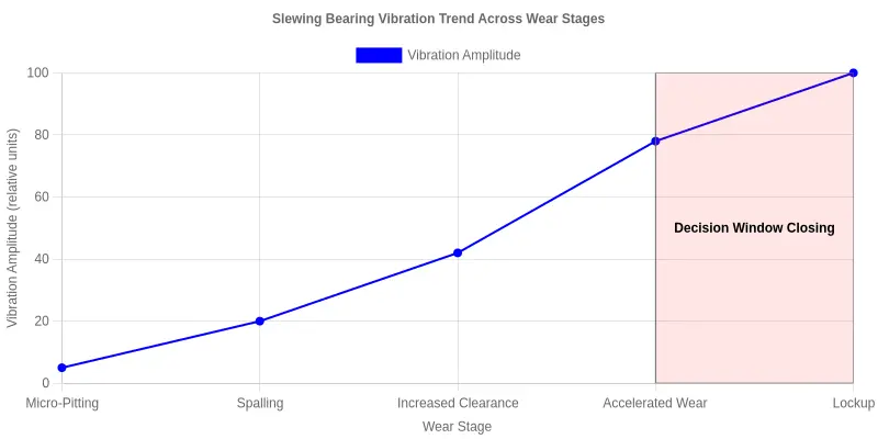
A slewing bearing on a tower crane rarely fails without warning. It warns you for weeks, sometimes months, in a language written in vibration. The problem is that few people are listening until the crane refuses to swing. Here is the arc of that decline, stage by stage, and how the vibration signature shifts at each turn.
Stage 1: Micro-Pitting and Surface Fatigue
It begins invisibly. Under millions of rolling cycles, microscopic fatigue cracks open just beneath the raceway surface, and tiny pits form. In your vibration data, this reads as a faint, high-frequency ripple that most technicians dismiss as background noise. It is not noise, and it does not stay quiet.
Stage 2: Spalling and Material Loss
As those micro-pits connect, whole flakes of hardened steel break away. This is spalling, and it changes the signal: sharp, repeating impacts appear at the bearing’s characteristic fault frequencies. The vibration trend, which until now was a flat, boring line, takes its first unmistakable rise.
Stage 3: Increased Clearance and Misalignment
With material gone, the bearing no longer fits the job it was built for. Internal clearance widens, the raceway misaligns, and load shifts onto fewer rollers. The vibration pattern smears into broader, lower-frequency bands, and sidebands appear around the original fault peaks. Grease darkens with fine metallic dust.
Stage 4: Accelerated Deterioration
Once misalignment takes hold, decay compounds: amplitudes climb steeply, harmonics multiply, and the vibration trend turns nearly vertical. What once took months now happens in days, or in a single shift.
Stage 5: Lockup
Finally, the bearing loses its ability to rotate. Metal grinds on metal until motion stops entirely. This is lockup: the crane cannot slew, production halts, and the repair bill reaches its maximum. Vibration monitoring is useless at this point; the machine is already down.
The Window That Matters
The chart above shows the gap between the first micro-pit and full lockup, and that gap is the only place where maintenance decisions can still be made on your terms. Detecting the rising trend early buys weeks to schedule a repair during planned downtime. Miss it, and you inherit an emergency at the worst possible moment.
Vibration Amplitude Trend Toward Slewing Bearing Lockup
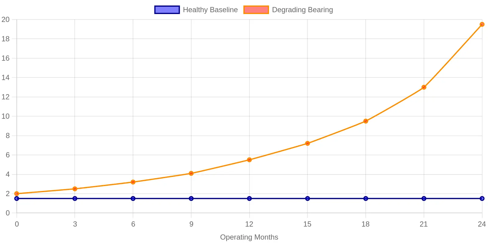
The degrading bearing tracks close to the healthy baseline early on, and the two lines separate as wear accumulates. That widening gap, capped by a sharp spike at month 24, is the warning that the bearing is approaching lockup.
Where to Mount Sensors and What to Record
You cannot diagnose a failing slewing bearing by listening to the machine once. What matters is the right accelerometer placement, clean vibration data, and a known baseline reading to compare against.
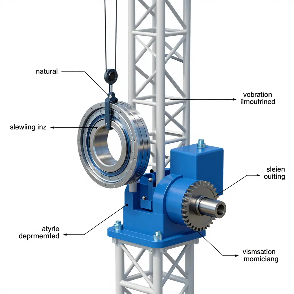
Recommended accelerometer placement
For a slewing assembly, mount sensors at these priority points:
- On the slewing ring / bearing race housing, horizontally, close to the load path.
- On the slewing drive gearbox housing, near the output shaft bearing.
- On the pinion bearing cap, where gear-mesh faults show up first.
- On the adjacent structure, only as a reference to isolate external noise.
Keep sensors magnetically or stud-mounted and as close to the source as possible. Hand-held probes add variability you do not want in the record.
Why mounting orientation matters
A bearing defect that fires sideways looks faint on a vertical axis. Always record the axis of each sensor (radial, axial, tangential) and keep it identical between visits. Rotate a sensor 90 degrees on the next inspection and the numbers shift for reasons that have nothing to do with wear. Consistent orientation makes your history trustworthy.
Sampling rates and frequency ranges
Low-speed slewing is a tricky measurement target. The bearing spins slowly, so the faults of interest sit at low frequencies, but gear-mesh and structural details reach higher.
| Parameter | Recommended setting |
|---|---|
| Frequency range of interest | 0.5 Hz to 2 kHz |
| Minimum sampling rate | 2.56 x top frequency (at least 5 kHz) |
| High-resolution / envelope band | 0.5 to 10 kHz for bearing impact tones |
| Logging interval | Every 50-100 operating hours, plus after any alarm |
Avoid setting the sampling rate too low. Aliasing will fold high-frequency bearing impacts into your low-frequency bands and create phantom faults.
Data logging intervals
Sample on a schedule, not just when something sounds wrong. A reading every 50 to 100 operating hours works for most sites, plus a fresh capture after any shock load, overload event, or unusual noise report.
Log the date, lift configuration, load, ambient temperature, and sensor axis alongside every capture. Context turns a number into a diagnosis.
Building a baseline reading
A baseline is simply the vibration signature of a healthy bearing doing its normal work. Take three or four clean captures over the first week of operation under similar loads, average them, and record the result as your reference point. Slew speed, wind, and load radius all shift the signature, so keep conditions comparable.
Why trending beats one-off measurements
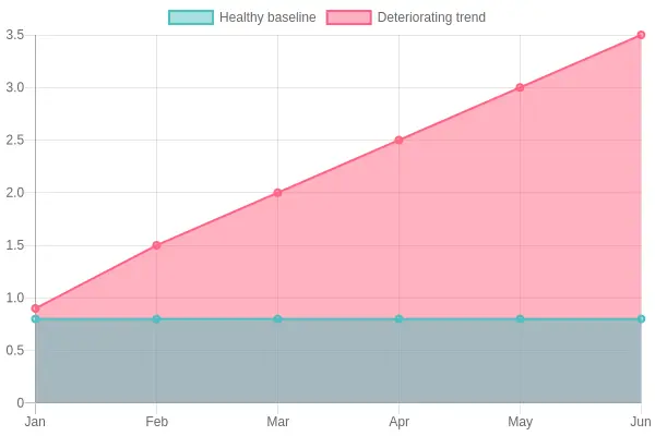
A single reading tells you almost nothing, because so many factors move the numbers up and down. Trending shows direction and rate.
The chart below contrasts a steady healthy baseline with a bearing that is slowly failing. On any single day the difference can look small; the trend is unmistakable.
Practical tips for keeping records consistent
- Use the same sensor, mount, and axis every time.
- Note the exact mounting location in a photo or sketch.
- Standardize units and instrument settings across the fleet.
- Review the trend after every capture, not once a year.
- Flag any rise above roughly two to three times baseline for closer inspection.
Consistency is what turns scattered readings into a warning system, giving you time to plan a repair instead of reacting to a lockup.
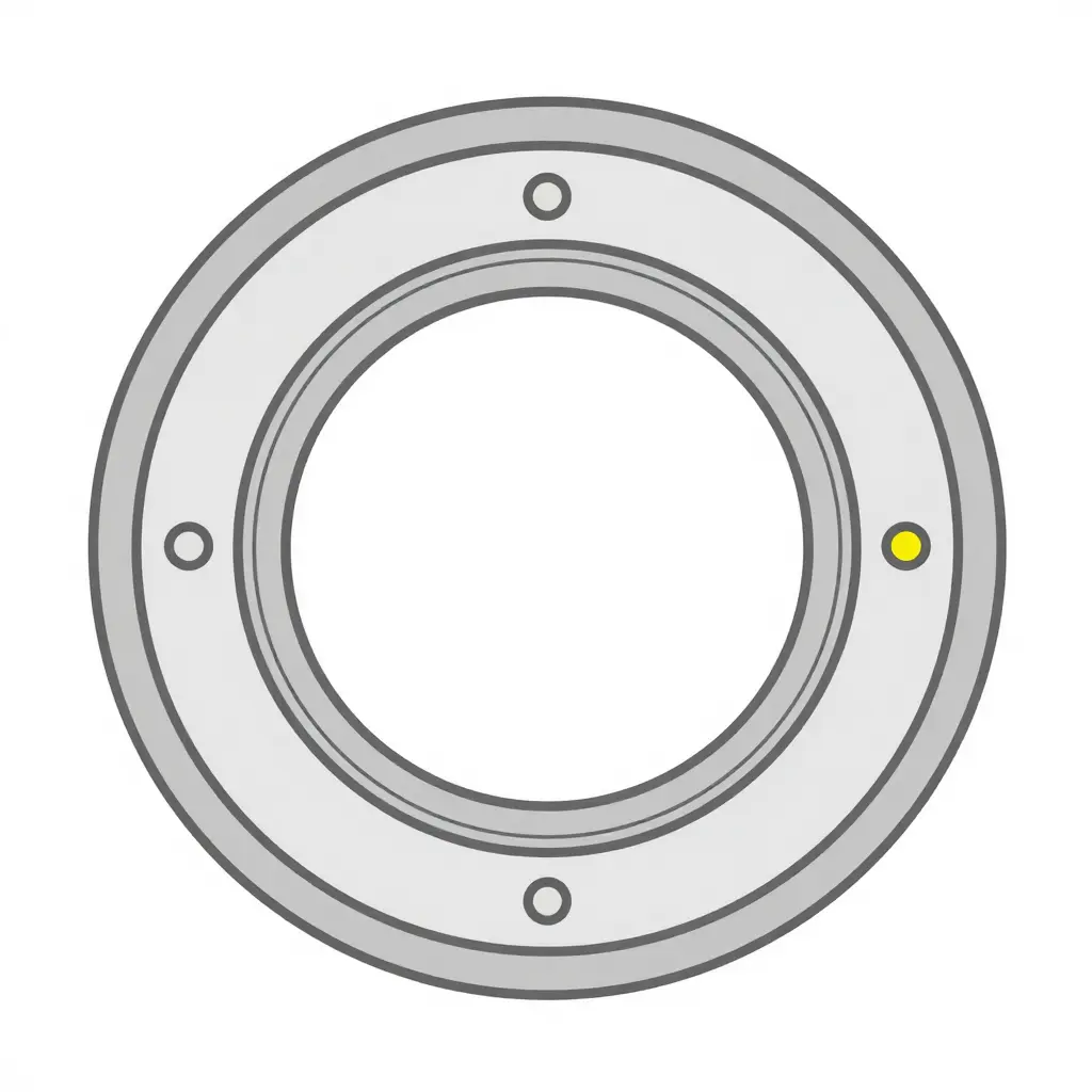
Where the Sensors Sit Around the Ring
The schematic above is a top view of a slewing assembly, with markers showing typical sensor mounting positions around the bearing ring. Spreading sensors across the circumference lets you compare vibration signatures from different quadrants, so a localized wear pattern or a developing flat spot shows up as a rising signal in one direction rather than a blanket increase everywhere.
Turning Raw Readings Into Actionable Alarms
A raw vibration number is only useful once it drives a decision, and that starts with a baseline rather than a fixed absolute value.
Every crane settles into its own normal rhythm. Record readings during steady slewing, light hoisting, and heavy picks, then average them over a few weeks of healthy operation. That rolling average becomes your reference point, so your vibration threshold moves with the machine instead of with a generic spec sheet. Fixed absolute values miss the slow drift that signals early tower crane slewing bearing wear: the bearing can degrade steadily while still sitting inside a factory number.
Load and operating conditions matter just as much. A reading taken mid-swing under a full bucket is not the same as one taken at idle, so always tag each measurement with load, radius, and slew speed. Compare like with like.
Trend slope is the leading indicator. A single high reading is noise; a steadily climbing line across ten or twenty shifts is a story. Watch the angle of that climb, not just where it lands today.
Setting Tiered Alarm Levels
A good alarm level system escalates before a lockup becomes likely, giving the team room to inspect on its own schedule.
| Alarm Level | Trigger Condition | Action |
|---|---|---|
| Watch | Reading 20% above rolling baseline | Log it, review next shift |
| Warning | 50% above baseline, or slope rising for 3 shifts | Schedule bearing inspection |
| Danger | 100% above baseline, or sudden jump | Stop slewing, inspect immediately |
Keep each tier tied to a clear action, and review the triggers quarterly as the machine ages. A system like this flags a tired bearing weeks before it grinds to a halt.
Frequently Asked Questions
How often should vibration data be collected?
For most tower cranes in regular service, collecting vibration data once per shift, or at least weekly, gives you a reliable baseline. Machines on heavy duty cycles or exposed to harsh weather may need daily sampling. The goal is to build a trend line rather than chase a single snapshot, so consistency matters more than raw frequency.
Can vibration monitoring catch a fault before lockup?
Yes, that is exactly the value of early monitoring. A worn raceway or failing gear typically produces rising vibration signatures weeks before the slewing bearing seizes into a dangerous lockup. By trending those signals, technicians can schedule service during planned downtime instead of reacting to an unplanned failure on site.
What is the most common cause of slewing bearing wear?
In tower cranes, inadequate or contaminated lubrication is the leading culprit, followed by uneven loading and misalignment. When grease breaks down, metal-to-metal contact accelerates and the slewing bearing degrades faster than any inspection schedule expects. Regular greasing and alignment checks remain the cheapest protection you can buy.
How do temperature and vibration data work together?
Temperature catches slow-burn problems like friction and failing lubrication, while vibration data reveals the sharp, high-frequency signatures of spalling or a cracked raceway. Read together, they tell a fuller story: a rising reading plus new vibration spikes usually confirms a developing fault. Neither signal alone is as convincing as the two combined.
Does a single high reading mean the bearing is failing?
Not necessarily. One spike can come from a gust of wind, a sudden load swing, or a sensor glitch. What matters is the trend: two or three elevated readings in a row, especially alongside rising temperature, warrant a closer inspection before you worry about a lockup. Treat a lone spike as a prompt to re-measure, not a verdict.
Responding to the Data: Inspection and Intervention
When vibration signatures trend upward, you are not diagnosing a problem yet; you are buying time. Move through the same sequence every time so nothing gets skipped.
Confirm the signal. Book a scheduled inspection within days, not weeks. Re-read the same slew points under the same load and radius to confirm the trend is real and not a one-off reading.
Sample the lubricant. Pull a grease or oil sample for lab analysis. Look for rising iron and copper particles, water ingress, and viscosity breakdown. Particle counts tell you whether wear is active or still surface-level.
Correct the mechanical setup. Re-torque mounting bolts to spec and re-shim to restore clearances and alignment. These low-cost fixes often flatten a rising trend on their own.
Plan the bearing replacement. If analysis shows spalling or advanced fatigue, schedule the swap during a controlled shutdown. A bearing replaced on your terms costs far less than one that ends in a sudden lockup mid-lift.
Prioritizing Repair Timing by Trend Severity
Use the slope of the trend, not a single number, to set priority:
| Vibration Trend | Action Window | Priority |
|---|---|---|
| Stable baseline | Routine preventive maintenance | Low |
| Slight, steady rise | Scheduled inspection plus lubrication | Medium |
| Rapid rise | Immediate inspection, book the swap | High |
| Spikes plus rumbling | Stop use, isolate the crane | Critical |
Keep the log current. Trend severity only means something against history, so record every reading, fix, and part change. Consistent preventive maintenance is what turns a looming failure into a planned afternoon of work instead of a forced, days-long shutdown.
Conclusion: Turning Surprises into Scheduled Maintenance
Every catastrophic lockup tells the same story in hindsight: the warning signs were there, but nobody was reading them. By now the path should feel familiar. It runs from the mechanics of tower crane slewing bearing wear – how rolling elements, raceways, and lubrication break down long before a crane refuses to swing – to the practical work: placing sensors where they capture meaningful motion, trending vibration data over weeks and months to catch the slow drift a single snapshot hides, and setting thresholds that turn raw numbers into decisions. Each step builds on the last, and together they move maintenance from reactive firefighting to a planned routine.
When a bearing does reach the end of its service life, you already know it is coming. You have the parts on hand, you schedule the swap during a quiet window, and you avoid the overnight scramble that follows an unexpected failure. That is the real payoff of condition monitoring: fewer emergencies, safer lifts, and equipment that keeps earning its keep. As more sites adopt continuous monitoring and better analytics, that value only grows, protecting both the people working below the boom and the uptime your project schedule depends on.